MIDIfying a YMZ702 based keyboard
(english version below)
Den ein- oder andere DIY Mitstreiter in der Synthesizer- oder MIDI-Liga hat vielleicht schon einmal das Interesse an einem selbstgebauten Keyboard gepackt, oder beim Ausschlachten eines E-Pianos von Yamaha erschien einem die Entsorgung der Tastatur irgendwie als nicht angebracht, weil sie vielleicht noch einem Besserem bestimmt sein könnte.
In der Tat erscheinen die Tastaturen von Yamaha – ob E-Piano, Keyboards oder Synthesizer – als durchaus recht angenehm im Spielgefühl und wer schon mal in die Zwangslage kam (ich würde es eher als Genuss bezeichnen), einen Synthesizer eines anderen Herstellers zerlegen zu müssen, dem ist möglicherweise ins Auge gefallen, dass die dort verbaute Tastatur ggf. von Yamaha stammt. Korg ist da z.B. so ein Kandidat, aber auch andere.
Schaut man sich die Tastaturen von Yamaha genauer an, dann überraschen diese mit angenehm wenigen Anschlüssen und die Platine ziert ein 40-pinniger Baustein mit der Aufschrift YMZ 702-D. Dies einlädt geradezu ein, sich im Rahmen eines Selbstbauprojekts damit näher zu beschäftigen. Stellt sich nur die Frage, wie man dieser Tastatur MIDI beibringt? Und genau darum geht es in diesem Artikel…
Bei genauer Betrachtung des Problems ist ein wenig Reverse-Engineering von Nöten um zu verstehen, welcher Anschluss welchen Zweck erfüllt. Ein Datenblatt von dem IC war bisher nicht zu bekommen. Das einzige, was aufzutreiben war, war ein Service Manual eines CLP-920 E-Pianos, was die gewichtete Tastatur GHD88 verwendet. Darüber hinaus habe ich die Seite von Paul Banks im Internet gefunden, der bereits einige sehe hilfreiche Vorarbeiten geleistet und dokumentiert hatte. Dies hat er in einer Art Datenblatt für den YMZ702 zusammengefasst.
Wie Paul Banks bereits beschreibt ist nach dem Einschalten der Spannungsversorgung von 5V zunächst eine Initialisierung des YMZ702-D Bausteins an dessen Pin 24 erforderlich. Die genaue Bedeutung der Sequenz ließ sich bisher leider nicht entschlüsseln, es schein sind aber um ein synchrones serielles Telegramm mit ca. 100kBaud zu handeln, allerdings mit überlagertertem Clock-Signal. Hält man sich jedoch an das, was Paul beschreibt, funktioniert anschließend alles wie ab hier beschrieben:
Nach der Initialisierung liefert der YMZ702 auf Pin 23 synchrone serielle Daten mit 1MHz Übertragungsrate. Diese lassen sich z.B. sehr gut über den SPI Eingang (MOSI bei einem Slave bzw. MISO bei einem Master) eines Controllers empfangen. Auf Pin 25 liefert der YMZ702 das notwendige Clock-Signal (SCLK). Eine Besonderheit ist, dass jedes empfangene Datenbyte durch einen kurzen LO-Puls an Pin 24 quittiert werden muss, da ansonsten keine weiteren Daten mehr vom YMZ702 versendet werden (Achtung: Beschreibung von Paul ist hier nicht ganz korrekt). Eine weitere Besonderheit ist, dass Reihenfolge der Bits gegenüber SPI vertauscht ist, d.h. im seriellen Datenstrom wird zuerst das LSB übertragen und zuletzt das MSB (keine Ahnung, was sich die YAMAHA Entwickler dabei gedacht haben). Für jede neu gedrückte als auch losgelassene Taste überträgt der YMZ702 jeweils drei Datenbytes.
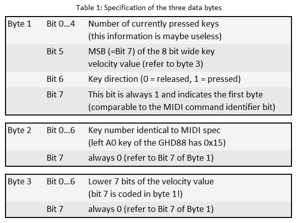
Der eigentliche Clou des Reverse-Engineerings lag in der Interpretation dieser drei Datenbytes (siehe Tabelle weiter unten). Das Datenpaket beinhaltet die Nummer der Taste, einen Wert für die Anschlagdynamik, die Richtung der Taste (gedrückt oder losgelassen) sowie die Anzahl der aktuell gedrückten Tasten.
Der übertragene Wert für die Taste entspricht bereits exakt der MIDI Spezifikation, also z.B. 0x15hex für das A0 ganz links auf der GHD88 Tastatur. Hier muss also nichts weiter übersetzt werden. Der Wert für die Anschlagdynamik scheint ein 8-Bit Aufwärtszähler zu sein. D.h. kleine Werte entsprechen einer hohen Velocity. Hier muss man umrechnen und kann mit verschiedenen Charakteristiken experimentieren, um eine angenehmes Spielgefühl zu erhalten. Eine weitere Besonderheit ist, dass auch für eine losgelassene Taste ein Velocitywert übertragen wird. Hier sieht die MIDI Spezifikation ohnehin zwei Lösungen zum Übertragen einer losgelassenen Taste vor. Entweder überträgt man dafür ein Note On Command mit der Velocity 0, oder man überträgt tatsächlich den Note Off Command, der eine Velocity enthalten kann. Nur wenige Synthesizer werten diese Funktionalität tatsächlich aus. Mein Roland JD990 kann aber sehr wohl etwas damit anfangen :-).
Nachdem nun die Bedeutung und Funktion der einzelnen Anschüsse und der übertragenen Daten klar ist, bedarf es nun eines kleinen Controllers, der eine SPI und eine UART beinhaltet, damit die Daten des YMZ702-D in brauchbare MIDI Daten umgewandelt werden können.
Zu diesem Zweck habe ich meinen bevorzugten Controller für kleine MIDI Adaptionen herangezogen, einen ATtiny4313 von Atmel. Da dieser neben der SPI-Schnittstelle und dem gewünschten UART noch ausreichend I/O Pins übrig hatte, habe ich meine Softwarelösung etwas komfortabler gestaltet. Über vier Pins kann der MIDI Kanal binär eingestellt werden. Über zwei weitere Pins können unterschiedliche Charakteristiken für die Anschlagdynamik ausgewählt werden. Ein Pin fungiert als Anschluss für ein Haltepedal. Da der serielle Eingang der UART ansonsten keinen nutzen hat, habe ich zudem eine MIDI-Merge Funktionalität implementiert, d.h. die Lösung verfügt zudem über ein MIDI-In und damit auch über einen MIDI-Thru Anschluss. Somit kann die Lösung auch in eine vorhandene MIDI Leitung eingeschliffen werden oder für den Aufbau einer mehrmanualigen Orgeltastatur können zwei oder mehr Tastaturen kaskadiert werden.
Für die Hardware steht ein Schaltplan als Download zur Verfügung. Dies ist sicher nur als Beispiel zu sehen und kann nach eigenen Wünschen entsprechend adaptiert werden. Das Projekt habe ich in EAGLE umgesetzt. Ein Layoutvorschlag gibt es ebenfalls als Download. Die Software hingegen stelle ich nicht als Download zur Verfügung, weil diese ansonsten schnell von anderen käuflich vertrieben werden wird. Ich denke, ich habe mit meinen Beschreibungen aber jedem die Möglichkeit gegeben, sich etwas Vergleichbares selber zu programmieren.
Wer sich die Arbeit dennoch sparen möchte, kann gegen eine Schutzgebühr von 15€ gerne einen programmierten Controller von mir zugeschickt bekommen. Auch habe ich noch fertige Platinen herumliegen, die ich auf Wunsch ebenfalls für 7€ abgeben kann. Wer Interesse hat, kann sich gerne über das Kontaktformular bei mir melden. Bitte nur Anfragen auf Deutsch oder Englisch – andere Sprachen habe ich nicht installiert 😉
Maybe electronic experts with some DIY ambitions in the fields of music synthesizers or MIDI sometimes think about building their own keyboard or when disassembling an old keyboard you thought the keyboard itself still has some value and should be re-used for any new project instead of throwing everything away.
Indeed, keyboards by Yamaha – used in e-pianos or synthesizers – offer a very realistic feeling and if you ever had the chance to disassemble a keyboard from any other manufacturer maybe identified that most of the keyboards inside are producedby Yamaha. e.g. Korg offers instruments containing such keyboards from Yamaha.
While analyzing a Yamaha keyboard, then you’ll be surprised about the low number of connecting pins to the main electronics and the PCB on the keyboard is mainly based on an interesting device called YMZ 702-D. This design looks really very nice and invited to any kind of DIY project. But how to teach it MIDI? And that’s exactly what this article is about…
When digging into the details, some reverse engineering is needed to understand, which pin from the keyboard’s PCB to the main PCB has got which function. Any kind of datasheet of the YMZ 702-D was not available on the internet. The only thing which was available were some service manuals of a few Yamaha e-pianos like the CP-90 E, which uses the very nice GHD88 keyboard with excellent weighted keys. On top of this I found the website of Paul Banks. This smart guy already started with some reverse engineering activities and he was so kind to document everything which he did and disclosed a PDF on his website. This PDF is something like a datasheet for the YMZ 702-D and contains some very helpful details.
As Paul has written in his documentation, the YMZ702 works with 5V DC and after powering-up the device there is some serial initialization sequence necessary on pin 24. Unfortunately, the exact meaning of that sequence could not be decoded, but it looks like synchronous communication with about 100kBaud, but with an underlying clock information. Even when not understanding the details of the communication, until you’re “re-drawing” this sequence exactly in the way Paul described, the device starts to work like this:
After initialization is done the YMZ702 provides a synchronous serial communication with 1MHz data rate on pin 23. This data can be read e.g. by using the input of a conventional SPI interface (MOSI on a slave or MISO on a SPI master device). The YMZ702 provides the data clock signal on pin 25 which should be connected to the SCLK of the SPI interface. Any single transmitted data byte coming from the YMZ702 need to be acknowledged by a short LO pulse on pin 24, which was previously used for the initialization sequence, before the device transmits the next data byte (attention: this is not described correctly in Paul’s documentation). One idiosyncrasy is that the funny guys from Yamaha are using the wrong bit order compared to SPI. That means the LSB is coming first, so you need to swap the bit order before processing the incoming data.
The device transmits three data bytes per pressed or released key. The key part of my reverse engineering activity was to understand the meaning of the three bytes (see table below). Summarized, the data contains a number for the key, a value for the key velocity, the key’s direction (pressed or released) and the amount of currently pressed keys.
The transmitted key number already fits perfect to the MIDI specification like 0x15hex for the lowest A0 key on the left side of the GHD88 keyboard, so no need for any post-processing here. The value for the key velocity is an 8 bit upwards counter which means high velocity generates small values. This definitely needs some post processing and you need to play a bit with the characteristics for realizing the best possible control or feeling of the keyboard. Interestingly, released keys are also providing a velocity value. This is quite nice, because the MIDI specification provides two options for transmitting a released key – one is the Note On event with velocity 0 (common use in the MIDI world) and the option is the Note Off event, where you indeed can transmit a release velocity. Unfortunately, most synthesizers or keyboards do not use the release velocity, but luckily my Roland JD990 understands this and can control the envelopes by this value :-).
After the different pins and the data stream is understood, you just need any tiny controller which contains a SPI interface as well as an UART to translate the YMZ702 data into useful MIDI messages.
For this I took an ATMEL ATtiny4313 AVR controller which I already used a couple of time for some inline modification of MIDI data. On top of the needed SPI and UART, this device offers some useful I/O pins. In my solution I took four pins for selecting the MIDI channel, one pin as input for a Damper Pedal and two pins for switching between different characteristics of the key velocity. As the input of the UART is not used, I also implemented a MIDI merge function. Therefore my solutions also contains a MIDI-in as well as a MIDI-thru connector. This is very helpful when e.g. connecting this solution in between a rack synthesizer and another keyboard or in case of cascading multiple keyboards for building up an organ with two or more manuals.
I provide all documentation of the hardware I developed. The schematics is available as download and can be used as an example. I used EAGLE and the project data is as well available for download. I also offer a layout proposal for the PCB I’m using. The only thing I do not provide is my software solution. The reason is quite easy, because there are lots of people around the globe steeling solutions from others and selling this which I definitely do not support. But I think everyone can easily realize his own solution based on my documentation.
If you would like to save your time or you’re not such familiar with C or Assembler, I offer a programmed controller for 15€. I also do have a few professional bare PCBs on stock which I can offer for additional 7€. If you’re interested in getting these parts or if you still have some questions, you can contact me via the contact form on our website. Please use only use German or English language – other options are not yet installed in my head 😉